Bottle Rocket
| Race Order |
Entry # | Driver Name | Car Name | Mass (grams) |
Length (inches) |
Width (inches) |
Height (inches) |
Distance Traveled (feet) |
Running Time (seconds) |
Awards |
| 12 | 30 | Mike Blakely | Bottle Rocket | 394 | 72 | 6 | 4.3 | 47.92 | 6.16 | 3rd Farthest Distance & Most Creative & Largest |
Balloon car designer Mike Blakely writes:
- Design approach taken – explain how it worked.
This design attempted to harness as much energy as possible from the
deflating balloons by having their escaping air feed into a chamber which
would grow in volume by having a surface which moved against a load. The
work done on that moving surface by the deflating balloons was to be coupled
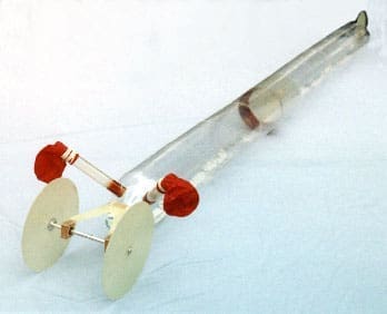
to the driving axle of the car with as little loss as practical.The moving surface took the form of a cone-shaped piston in a tube, and the
force of the piston was applied against a thin line which was wound around
the driving axle. The tube just mentioned also served as the body of the
car, with a single wheel running on a ball bearing in front and two wheels
in the rear attached to an axle which turned in two of the same ball bearings. - Unique or clever features embodied
Starting with the balloons, they were to be exhausted efficiently by
avoiding unnecessary throttling and turbulence in their outflow. To
accomplish this, large-diameter tubes (3/4 inch) were installed all the
way through the stems of the balloons to hold them open.The piston incorporated a flexible skirt of overlapping pieces of Kapton
sheet. Paper works as well but is much less durable and seemed to have more
friction against the tube. - Materials of construction (mention unique parts you used or fabricated)
The body/cylinder of the car was made from 2-liter Pepsi bottles, very
carefully
cut, fit together and taped around the circumference. The balloon exhaust
tubes
came from the remains of a fish aquarium filter. The piston is made from
.007″
epoxy-glass sheet, rolled into a cone and lap bonded with quick-setting epoxy.
A piston stabilizer ring is made from .015″ epoxy-glass and prevents the
piston
from cocking in the tube. The apex of the cone piston is slightly
truncated and
capped with a small disk of .031″ epoxy-glass; it is this disk which supports
the tensile load of the .010″-diameter fishing line which runs back and around
the rear axle.All wheels, just under 6″ diameter, are made from .031″ epoxy-glass. The rear
suspension yoke is also epoxy-glass (we love it) .045″ thick. Rear axle
bearings
are a light press fit into tapered holes in wooden pillow blocks which are
bonded
with epoxy to the yoke. The front wheel bearing is pressed into the wheel
itself.
The rear axle is made from 1/4″ aluminum rod and the wheels attach with #10-32
aluminum screws. - Reasons behind any significant design choices you had to make
One major choice was the tubing/car body diameter. Larger diameter had the
benefit
of requiring less piston travel to exhaust the balloons, but would result
in larger
piston force and would need larger wheels to keep the tube clear of the
ground.
Smaller tubing had the advantage of producing less piston force, allowing
lighter
construction of some components, but to fully utilize the air from two
balloons
the overall length of the car became unreasonable with diameters under 4
inches.
In the end, this issue was settled by the practical availability of light
tubing;
2-liter Pepsi bottles are about 4.3″ diameter and cost little. But now the
problem
of the inevitable imperfect joint between bottles, and variations in
diameter…The choice of a cone for the piston solved that problem. The thin cone
itself is
flexible and can easily be squeezed into an oval shape at its base; it
still works
fine if the tubing is far from round. But the tubing also had variations
in its
molded diameter, as much as .02″, so a simple cone could never be expected
to seal
properly along the length of the car. That was solved by making the piston
slightly
undersize and then adding a flexible skirt to follow the tubing
irregularities. The
skirt provides a positive seal in that, the more the pressure behind it,
the more the
skirt presses against the wall of the tube. The friction of the Kapton
skirt against
the plastic tubing turned out to be low so my plan to apply a thin film of
silicone
lubricant to the bore was abandoned. The piston force was already
threatening to
break the six-pound fishing line.Wheel diameter was mostly driven by the need to raise the car body off the
ground by
some safe distance, and I settled for a bit less than an inch of clearance.
Larger
diameter wheels were not used because six-inch wheels seemed more than
large enough
to travel smoothly over the course, and the car’s powered travel (while
piston is
applying torque to the axle) was already calculated to be a large figure
with respect
to the course – 110 to 120 feet depending on how well the fishing line was
wound on
the axle. With a fixed piston travel of 50″ and 1/4″ axle with small
groove to contain
the line wrapped in 5 or more layers, larger wheels to increase the travel
under power
seemed unnecessary. If the car were able to clear the narrow part of the
course and
achieve its 110 feet of powered travel, the free-running wheel bearings
were expected
to allow it to easily reach the end of the course. - Lessons learned (what you’d do differently next time)
Test, test, test because the steering (ability to run straight) needed
improvement.
That is easy to say, but the car was difficult to build to the necessary
standards and
there was very little time left, and always a chance of damage. Steering
alignment
was limited to several coasting tests, seemed OK, but was compromised by a
handling
mistake at the last moment. More tests could have revealed that weakness. - Anything else you’d like to add
Some interesting figures…
Pressure measurements were made of inflated balloons. A balloon inflating
for the first
time needed about 30 Torr for inflation. While deflating, pressure would
stay around
20 Torr. A very tired balloon deflating produced a minimum of 10 Torr.
Remember 760 Torr
is one atmosphere, 14.7 psi, so my design pressure was between 0.19 psi and
0.39 psi.The piston area is that of a 4.3″ diameter circle, 14.5 square inches, so
the force on the
piston from the above pressure is from 2.75 to 5.5 pounds. Not bad if
friction doesn’t
eat much up (it doesn’t).Piston travel is 50 inches at full pressure and is physically stopped
there. The deflating
balloons do work on the moving piston, and work = force x distance. Let’s
assume a force of
3 pounds over 50 inches of piston travel. That is 150 in.lb of work. What
can that work do?
If we ignore losses such as rolling and air resistance, we can do a simple
calculation of the
peak velocity of the car. Of course air resistance is significant with
those balloons dragged
along, but let’s ignore it because the calculations are much simpler and
the answer is more
surprising.Assume the work, 150 lb.in, is all converted to kinetic energy T, where
T=1/2 MV*2, M being
the mass of the car and V is the velocity of the car. (A full accounting
of the kinetic energy
of the car should include rotation of the wheels and axle, where T=1/2
Iw*2, I being moment of
inertia and w being angular velocity in radians per second. Again, let’s
ignore this term.)
Let’s work with pounds, inches and seconds. The car weighs 0.8 pounds, but
that is not M.
We need the M from W=MG where W is weight in pounds and G is acceleration
of gravity in
inches/second*2. We find that M = 0.8/386, or .00207 “mass units”. Now V
= [2×150/.00207]*1/2
= 380 inches/second = 31.7 feet/second. Wow! All those spectators who
were in the way should
be glad the car went into the wall instead of down the middle of the track!
MB 1/9/99